Learn how dowel bars transfer loads across concrete joints, reduce faulting, and support durable slabs with correct sizing, alignment, and installation.
Industrial Floor Rebar Example for Slab Work
A warehouse slab can look straightforward until forklifts, loaded racking, point loads, and saw-cut joints start dictating the reinforcement detail. This industrial floor rebar example is a practical way to understand how reinforcing steel is commonly organized in a slab-on-grade package before materials are ordered. It is not a substitute for the structural engineer’s drawings. Bar size, spacing, lap lengths, cover, joint treatment, and slab thickness must follow the issued project design and applicable local requirements.
What an industrial floor rebar example should show
For industrial work, the rebar plan needs to do more than state a bar diameter and spacing. It should show crews where steel goes, how it is supported, where it changes around openings, and how it relates to joints and thickened sections.
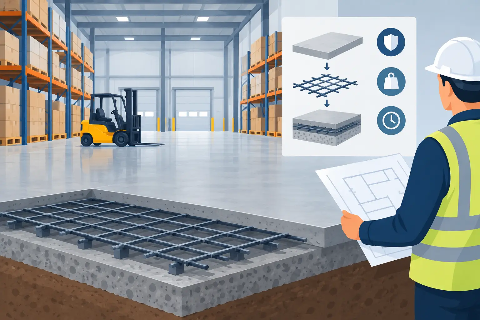
A useful example starts with the loading conditions. A light workshop with occasional vehicle traffic does not need the same slab detail as a distribution facility carrying high-bay racking and constant forklift traffic. The concrete mix, subbase preparation, slab thickness, joint layout, and reinforcement all work together. Rebar cannot correct a weak subgrade or poor joint planning.
Consider a hypothetical 10,000-square-foot equipment storage floor. The engineer may specify a 6-inch slab over a prepared granular base and vapor barrier, with a reinforcing mat of No. 4 bars at 12 inches on center each way. That works out to a grid of bars spaced 12 inches apart in both directions. The actual design could be lighter or heavier depending on the soil report, wheel loads, rack legs, and local code requirements.
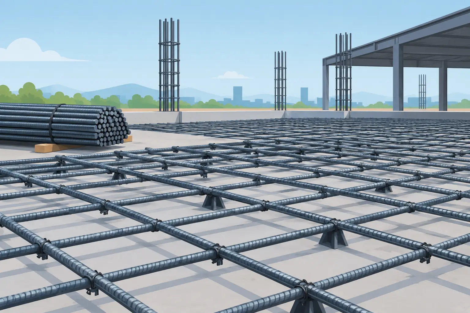
The key point is that the bars form a continuous mat, not a loose layer dropped onto the vapor barrier. The mat needs to sit at the elevation shown on the drawings so it can perform as designed when the slab cures and carries load.
A practical slab reinforcement layout
In this example, the field layout begins with two bar directions. One direction runs the full length of the building, while the crossing bars run the width. Crews normally choose a sequence that keeps the work area clear and reduces unnecessary cutting, but the final orientation should follow the plan.
At slab edges, the drawings may call for continuous perimeter bars, often with extra reinforcement at free edges, door openings, pits, or loading areas. These locations are more vulnerable to damage because they receive concentrated traffic and have less concrete confinement than the middle of the slab.
Around columns, rack footings, drains, and service penetrations, the regular grid may need to be trimmed and supplemented. Do not simply cut every bar that crosses an opening. The engineer may require diagonal bars at re-entrant corners, additional bars around blockouts, or bars placed each side of a penetration to maintain the intended reinforcement area.
Rebar schedule example
A basic material takeoff for the hypothetical floor could include the following items. Quantities are illustrative only and should be measured from the approved reinforcement drawings.
- No. 4 deformed rebar for the main slab mat at 12 inches on center each way
- Additional No. 4 or No. 5 bars for perimeter, openings, and thickened slab areas
- Approved tie wire for securing intersections and keeping the mat stable during placement
- Bar chairs or continuous supports sized to achieve the specified steel elevation
- Dowels, sleeves, or joint hardware where shown on the joint detail
For ordering, convert the grid into total linear feet of each bar mark, then allow for specified laps, hooks, waste, and cutting. A common mistake is to calculate only the clear floor dimensions. A bar that laps another bar or extends into a thickened edge needs additional length. Ordering from a bar schedule is cleaner than estimating from square footage alone.
Where the steel sits matters as much as the steel size
A rebar mat placed too low is one of the most common site failures. If the steel ends up resting on the vapor barrier, it will not provide the crack-control and load-transfer performance expected from the design. Pulling rebar up with hooks while concrete is being placed is not a reliable alternative to properly spaced supports.
The required position depends on the design. Some slabs use reinforcement near mid-depth, while others place steel higher in the section for crack control. Maintain the concrete cover called for on the drawings, particularly at slab edges and locations exposed to weather, soil, or chemicals.
Bar chairs need to support the reinforcement without puncturing the vapor barrier or sinking into a soft base. Plastic chairs are frequently selected over vapor barriers, while other chair types may suit different site conditions. Chair spacing depends on the bar size, mat weight, and traffic from the placing crew. If workers walking the steel causes the grid to deflect or drop, add support before the pour starts.
Tie intersections enough to keep the layout square and stable. Not every crossing must be tied unless the drawings require it, but perimeter bars, laps, opening details, and areas likely to be disturbed during placement deserve close attention. A neat, stable mat is faster to inspect and less likely to move when concrete arrives.
Laps, splices, and bar continuity
Rebar lengths are limited by stock length, delivery access, handling, and the site layout. That means many industrial slabs require lap splices. Lap length is not a rule of thumb. It varies with bar size, steel grade, concrete strength, coating, confinement, and the engineer’s design.
Keep lap locations where the drawings show them. If the detail allows staggered laps, avoid placing every splice on the same line. Staggering reduces congestion and prevents one narrow strip of slab from having too much overlapping steel at once.
Do not field-weld reinforcing bars unless welding is specifically permitted and the material is suitable for it. Welding the wrong bar can affect its properties. Where continuity is needed but lap space is limited, the engineer may specify mechanical couplers or a revised detail.
Joints are part of the reinforcement plan
Industrial floors are designed to crack in controlled locations, not to remain completely crack-free. Saw-cut control joints create planned weak planes so shrinkage cracks are more likely to form below the cut rather than randomly across the slab surface.
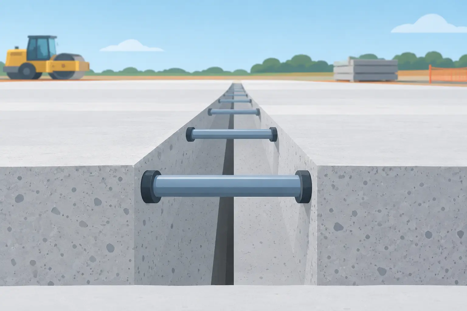
The rebar layout must work with those joints. In many slab-on-ground designs, continuous reinforcing steel passes through saw-cut control joints because the steel is intended to hold cracks tight after they form. Construction joints and isolation joints are different. They may need dowels, sleeves, bond breakers, or complete separation, depending on the detail.
Never assume that every joint gets the same treatment. Cutting through bars that were intended to remain continuous, or running steel through an isolation joint without the correct detail, can create expensive problems. Review the joint plan with the rebar plan before installation, not after the crew has tied the full mat.
Before the concrete truck arrives
The best time to catch reinforcement issues is during the pre-pour inspection. Confirm bar marks and spacing against the drawings, check that laps are the specified length, and make sure extra bars at corners, openings, and edges are installed. Check cover and chair height, then verify that joint hardware, dowels, embedded items, and penetrations are in their final positions.
Also look at the practical site issues. Are rebar ends capped where workers could be exposed? Is the reinforcement clear of the planned pump line and access route? Has the vapor barrier been repaired where it was damaged? Are materials on site before the schedule tightens?
For a simple industrial floor rebar example, a square grid may appear easy to supply. The detail work is where time and material are often lost: extra bars, laps, supports, tie wire, joint components, and last-minute changes around penetrations. Order from approved drawings, keep the material schedule clear, and give the placing crew a stable reinforcement layout they can inspect with confidence before the pour begins.
Related Posts